
8216cnc01
PERFORMANCE OF TCP CONGESTION CONTROL IN UAV NETWORKS OF VARIOUS RADIO PROPAGATION MODELS
Jun Peng
Electrical Engineering Department, University of Texas – Rio Grande Valley, Edinburg,
Texas, USA
ABSTRACT
Unmanned aerial vehicles (UAVs) have recently become popular for both recreational and commercial use and UAV networks have thus started to attract the attention of researchers in area of the computer communication and networking. One important topic in UAV networks is congestion control because congestion causes packet losses and delays which result in the waste of all types of network resources such as bandwidth and power. Although there are studies on the performance of TCP congestion control in wireless networks, they focus on terrestrial networks of two dimensions in general. In this paper we study the performance of TCP congestion control in three dimensional UAV networks. In particular, we investigate how TCP congestion control performs in such type of network using various radio propagation models. Our data on the average flow throughput, packet delay, and packet loss rate in UAV networks show that TCP congestion control improves the network performance of UAV networks in general, but it faces challenges when the link losses become severe. Our study thus shows that investigation on new congestion control schemes is stilled needed for the emerging UAV networks.
KEYWORDS
Congestion control, TCP, unmanned aerial vehicles (UAV), protocols, radio propagation
1. INTRODUCTION
Unmanned aerial vehicles were mainly used by the military but they have become popular for both civil and commercial use recently because relevant hardware and software has become more advanced but costs less at the same time. For example, various types of UAVs can be purchased for just hundreds of dollars in the market and they come equipped with advanced software and hardware. Some of these UAVs have high quality cameras preinstalled on them and people in all professions start to take advantage of them. Some examples are realtor using them to take aerial images and videos of properties for sale and enthusiastic amateur photographers taking pictures of their favorite scenes from the sky. The use of UAVs for taking aerial images and videos not only saves the huge cost of renting a plane or helicopter but also are faster to deploy and more friendly to the environment. Other areas where UAVs have been widely investigated and used include law enforcement, property surveillance, search and rescue in disasters, scientific research and other applications where terrestrial access is limited or impossible [1].
UAVs will eventually need to communicate with each other for all kinds of reasons such as coordination and collaborations. When there are more and more UAVs in the sky, it will become necessary for them to avoid collision among themselves. Although equipping them with radars can help, the extra cost and weight may make them not ideal for such a purpose. Some UAVs have already had GPS units installed on them and thus their location information may be used for
collision avoidance if the UAVs can communicate with each other in the sky in real time. There will also likely be some applications that need a big number of UAVs working together to achieve a goal. For example, when a large geographical area needs to fully surveilled without interruption for a period of time, one of the best solution would be a group of UAVs collaborating with each other on the job and relaying data back to the Internet. UAV networking will thus become more important in the near future.Researchers in the area of computer communication and networking have been investigating various topics at all layers of UAV networks. Asadpour et al. [2] studied the performance of IEEE 802.11n interfaces in UAV networks and they found that 802.11n performed poorly in highly
mobile scenarios. Cai et cal. [3] proposed a medium access control (MAC) protocol for UAV adhoc networks with fullduplex radios. They proposed a token-based technique to update information in the network for efficiently handling the high mobility of UAVs. Ollero et al. [4] presented a platform that enables autonomous aerial vehicles to cooperate with ground wireless sensor-actuator networks. Alshbatat et al. [5] used the approach of cross layer design to deal with the high dynamics in UAV networks. Alshbatat et al. [6] also proposed an adaptive medium access control protocol for UAV networks using directional antennas. Gu et al. [7] proposed arouting scheme for multi-layer ad hoc networks that use UAVs in their backbones. Gu et al. [8] also presented a multiple access protocol for such type of network.
One important topic in UAV networking that has not been widely investigated is congestion control. UAVs are widely used for capturing video and image data in all types of applications. When those data need to be sent over a UAV network, there will be heavy traffic on many links in the network which will likely cause congestion. If congestion occurs but is not dealt with in aUAV network, it will result in packet losses and delays and thus greatly degrade the performance of the network. The TCP congestion control is widely used in both wired and wireless networks.Although there is work investigating the performance of TCP congestion control in wireless networks [9], [10], [11], most investigation focused on terrestrial networks having two dimensions in general. In this paper we study the performance of TCP congestion control in UAV networks of three dimensions. It is well known that link losses in wireless networks cause performance problems for TCP congestion control. We thus investigated UAV networks having various link models in our study, which are the free space model, the two-ray ground model, and the shadowing model. Our conclusion is that TCP congestion control can improve the network performance of UAV networks, but when the link losses are severe, it faces significant challenges. It is thus still needed to design effective congestion control schemes for the emerging UAV networks.
The rest of the paper is organized as follows. Section 2 introduces the basic idea of TCP congestion control. Section 3 presents the three radio propagation models that we use in our study. Section 4 shows our results on the performance of TCP congestion control in UAV networks of various link models. Section 5 summarizes our findings.
2. TCP CONGESTION CONTROL
TCP congestion control is based on the approach of additive-increase multiplicative-decrease (AIMD) rate control, as shown in Figure 1 where the congestion window basically determines the rate of the TCP connection. TCP congestion control does not reply on the network for assistance in its rate control. Instead, it infers the congestion status in the network by monitoring the packet losses that a TCP connection experiences. When there are no packet losses, TCP increases its rate linearly, which is to ”explore” for free bandwidth that might be available on the path of the connection. When a packet loss event is detected, TCP cuts its rate by half to alleviate the congested status on its path. If no more packet losses are detected after the rate cut, it starts to increase its rate linearly again, since traffic on the connection’s path is dynamic and free bandwidth may become available any time. This AIMD approach has been proven effective in wired networks where congestion causes the most packet losses.
 Figure 1. The AIMD approach of congestion control [12]
When the TCP protocol is used in wireless networks, its congestion control faces the challenge of link losses caused by link impairments such as interference and fading. Since TCP congestion control interprets all losses as being aused by congestion, TCP cuts its rate by half whenever apacket loss event is detected, be it caused by congestion or link impairments. Depending on the characteristics of the link impairment in question, the decrease of the TCP rate may be helpful or harmful. If the link impairment is severe and lasts long, the reduction of TCP rate may actually help the situation because the effective bandwidth of the affected link would have decreased actually. However, when the link impairment is low in severity and short in duration, the halving of TCP rate may result in a much lower connection throughput than that the path can support. Emerging UAV networks have three dimensions in their node deployment and thus have more link complexity than two dimensional terrestrial wireless networks. It is therefore necessary to investigate how TCP congestion control would perform in UAV networks.
3. THE THREE RADIO PROPAGATION MODELS
In this section we introduce the three radio propagation models we use in our study. As introduced earlier, link losses pose challenges to TCP congestion control. Different link models introduce different link characteristics in UAV networks.
3.1. The Free Space Propagation Model
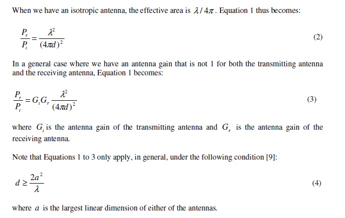
The free space radio propagation model assumes, as its’ name indicates, that the transmitter and the receiver are in free space without obstacles. The propagation formula is as follows [9]:

where r P is the signal power at the receiving antenna, t P is the signal power at the transmitting antenna, r A is the effective area of the receiving antenna, t A is the effective area of the transmitting antenna, d is the distance between the transmitting antenna and the receiving antenna, and l is the wavelength of the signal When we have an isotropic antenna, the effective area is l / 4p . Equation 1 thus becomes:

3.2. The Two-Ray Ground Propagation Model
The two-ray ground propagation model [10] assumes that there are two signal paths from the transmitter to the receiver. One is the direct line-of-sight path while the other is the reflection path from the ground. The formula is as follows:


3.3. The Shadowing Model
Due to multipath propagation effects, the received power at a receiving antenna is not a deterministic function of the communication distance as shown in the two models introduced earlier. Instead, the received power fluctuates as a random variable. The shadowing model [10] better reflects this characteristic of the received signal power than the other two models introduced earlier. The path loss is usually expressed in dB as follows in the the shadowing
model:


4. SIMULATION RESULTS
After introducing TCP congestion control and the three radio propagation models that we use in our study in preceding sections, in this section we investigate how TCP congestion control performs in UAV networks of various link models. The ns2 networking simulation platform [15] does not fully support the simulation of three dimensional networks. In our study we thus modified the ns2 package for simulating three dimensional UAV networks. The three dimensional test bed has the same size for its width, length, and height, which is 500 meters. UAVs are configured to fly freely in this defined space of three dimensions following therandom waypoint model. The UAVs in the test bed are configured to have the IEEE 802.11 air interface using its default settings in the simulator. During each simulation some UAVs set up TCP connections with some other UAVs at random times. Routing in the test bed is done by the DSR protocol [16].
 Table 1 Typical value of b in different environment
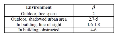
 Table 2 Typical value of d in different environment
The test bed used in our simulations has fifty UAV nodes flying in it. We varied the number of TCP flows in the network for each radio link model. In particular, we varied the number of TCP flows in the test bed from 10 to 35 for each model. In each simulation we collected data to calculate the average throughput of the TCP flows, the average loss rate of the TCP packets, and the average delay of the TCP packets in the network. The results are shown in Figures 2 to 10.
 Figure 2. The average TCP flow rate for the free space model
 Figure 3. The average TCP packet delay for the free space model
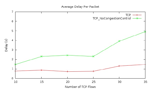
Figures 2 to 4 show the results for TCP flows in the UAV network using the free space link model. Figure 2 presents the average TCP flow rate in the network versus the number of TCP flows in the network. As mentioned earlier, the number of TCP flows varies from 10 to 35 in our simulations. There are two lines in the figure. One is for the TCP protocol with its congestion control enabled, while the other is for the TCP protocol with its congestion control disabled. As shown in the figure, the average TCP flow rate, in general, increases first with the increase of the number of TCP flows in the network and then starts to decease as the number of TCP flows increases further. This trend is true for both cases shown in the figure, with congestion control and without congestion control. However, one thing is obvious in Figure 2 is that when the TCP congestion control is disabled for the flows in the network, the average TCP flow rate is significantly lower. Therefore Figure 2 shows that TCP congestion control does improve the network performance in the case of our UAV network with free space link loss model.
 Figure 4. The average packet loss rate for the free space model
The results in Figure 2 are corroborated by the results shown in Figures 3 and 4. Figure 3 shows the average packet delay in the network using the free space link model. The average package delay, in general, increases with the number of TCP flows in the network because the traffic load is higher when there are more TCP flows in the network. Moreover, when the congestion control of TCP is disabled, the average packet delay is much higher than that when the congestion control is enabled. These delay results thus corroborate the throughput results shown earlier. Figure 4 presents the average packet loss rate for TCP flows in the network using the free space link model. As shown in the figure, the packet loss rate, in general, increases when there are more TCP flows in the network because a higher traffic load results in more and severer congestion events in the network. As in the case of average packet delay, the average packet loss rate is much higher when the TCP congestion control is disabled in the network. These packet loss results thus also demonstrate that TCP congestion control does improve the network performance in a UAV network where the free space link model is used, as the flow throughput and packet delay results show earlier.
 Fig. 5. The average TCP flow rate for the two-ray ground model
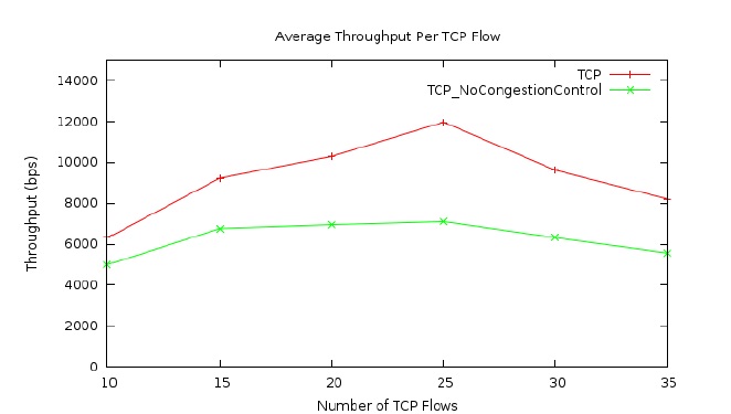
 Fig. 6. The average packet delay for the two-ray ground model
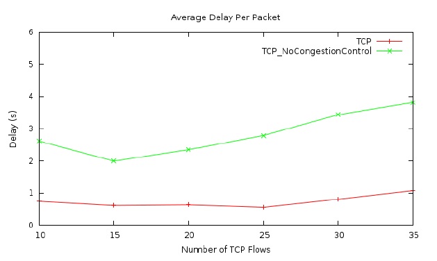
Figures 5 to 7 show the same kinds of results for the TCP flows in the UAV network as those in the previous three figures, but the wireless link model in the network has changed to the two-ray ground model introduced earlier. As shown in Figure 5, the average TCP flow rate increases first and then decreases as the number of TCP flows in the network increases from ten to thirty five, which is similar to the trend shown in Figure 2. Additionally, the average flow rate is much higher when the TCP congestion control is enabled in the network, which is also similar to what shown Figure 2. These throughput results are also corroborated by the packet delay and loss results presented in Figures 6 and 7, respectively. Figure 6 demonstrates that when TCP
congestion control is disabled, the average packet delay becomes much higher as compared that when the TCP congestion control is enabled. In addition, Figures 7 presents that when the TCP congestion control is disabled, the average packet loss rate is much higher than that when it is enabled. Therefore, in the case of the UAV network using the two-ray ground link model, TCP congestion control still significantly improves the performance of the network.
 Figure 7. The average packet loss rate for the two-ray ground model
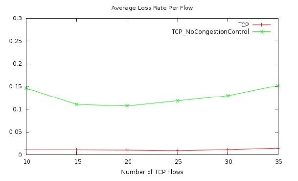
Figures 8 to 10 present the average flow throughput, packet delay, and packet loss rate, respectively, for the case where the shadowing link model is used in the UAV network. Although these results still demonstrate that TCP congestion control improves the performance of the network in general, the improvement becomes much less significant as compared with that in the other two cases of link models, the free space loss model and the two-ray ground model. As shown in Figure 8, the average flow rate of TCP flows in the network follows the same trend as that in the other two cases. However, the average flow rate in the case of disabled TCP congestion control is very close to that in the case of enabled TCP congestion control. Similarly, the average packet delay and loss results in Figures 9 and 10, respectively, show that the performance improvement generated by TCP congestion control is much smaller as compared with those shown in the two earlier cases of the free space loss model and the tworay ground model. It thus demonstrates that when the link losses are severe in an UAV network, TCP congestion control may face significant challenges. In summary, TCP congestion control can improve the network performance of an UAV network, but it faces significant challenges when the link losses in the network become severe. It is therefore important to investigate more effective congestion control schemes for emerging UAV networks.

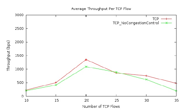
Figure 8. The average TCP flow rate for the shadowing model

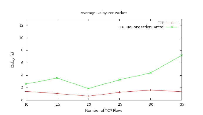
Figure 9. The average packet delay for the shadowing model
5. CONCLUSION
In this paper we study the performance of TCP congestion control in UAV networks using various link models. Although earlier studies show that TCP congestion control may face challenges in wireless networks, they are mainly done for two dimensional wireless networks. With UAVs becoming more and more popular for both recreational and commercial applications, more research efforts are needed in the area of three dimensional wireless networks. We investigated three dimensional UAV networks using three link models which are the free space model, the two-ray ground model, and the shadowing model. In particular, we studied how TCP congestion control impacts on the network performance in such type of network. Our results on average flow throughput, packet delay, and packet loss rate comprehensively show that TCP congestion control improves, in general, the network performance of an UAV network. However, when the link losses become severe, TCP congestion control faces significant challenges in UAV
networks. It is therefore needed to develop new congestion control schemes for emerging UAV networks.

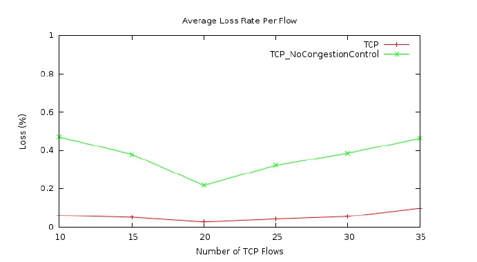
Figure 10. The average packet loss rate for the shadowing model
ACKNOWLEDGEMENTS
The authors would like to thank everyone who offered support to this project and the publication of its results.
REFERENCES
[1] T. H. Cox, C. J. Nagy, M. A. Skoog, and I. A. Somers, “Civil UAV Capability Assessment,” NASA,2004.
[2] M. Asadpour, D. Giustiniano, K. A. Hummel, and S. Heimlicher, “Characterizing 802.11N Aerial zCommunication,” in Proceedings of the Second ACM MobiHoc Workshop on Airborne Networks
and Communications, 2013, pp. 7–12.
[3] Y. Cai, F. Yu, J. Li, Y. Zhou, and L. Lamont, “Medium Access Control for Unmanned Aerial Vehicle (UAV) Ad-Hoc Networks With Full-Duplex Radios and Multipacket Reception Capability,” Vehicular Technology, IEEE Transactions on, vol. 62, pp. 390–394, Jan 2013.
[4] A. Ollero, M. Bernard, M. La Civita, L. van Hoesel, P. Marron, J. Lepley, and E. de Andres,“AWARE: Platform for Autonomous self-deploying and operation of Wireless sensor-actuator networks cooperating with unmanned eRialvehiclEs,” in Safety, Security and Rescue Robotics, 2007, IEEE International Workshop on, Sept 2007, pp. 1–6.
[5] A. Alshbatat and L. Dong, “Adaptive MAC protocol for UAV communication networks using directional antennas,” in Networking, Sensing and Control (ICNSC), 2010 International Conference on, April 2010, pp. 598–603.
[6] A. Alshbatat and L. Dong, “Cross layer design for mobile Ad-Hoc Unmanned Aerial Vehicle communication networks,” in Networking, Sensing and Control (ICNSC), 2010 International Conference on, April 2010, pp. 331–336.
[7] D. Gu, G. Pei, H. Ly, M. Gerla, and X. Hong, “Hierarchical routing for multi-layer ad-hoc wireless networks with UAVs,” in MILCOM 2000, vol. 1, 2000, pp. 310–314.
[8] D. Gu, H. Ly, X. Hong, M. Gerla, G. Pei, and Y.-Z. Lee, “C-ICAMA, a centralized intelligent channel assigned multiple access for multi-layer ad-hoc wireless networks with UAVs,” in Wireless Communications and Networking Confernce, 2000, IEEE, vol. 2, 2000, pp. 879–884.
[9] G. Holland and N. Vaidya, “Analysis of tcp performance over mobile ad hoc networks,” Wirel. Netw., vol. 8, no. 2/3, pp. 275–288, Mar. 2002.
[10] M. Gerla, K. Tang, and R. Bagrodia, “Tcp performance in wireless multi-hop networks,” in Mobile Computing Systems and Applications, 1999. Proceedings. WMCSA ’99. Second IEEE Workshop on, Feb 1999, pp. 41–50.
[11] G. Xylomenos, G. C. Polyzos, P. Mahonen, and M. Saaranen, “Tcp performance issues over wireless links,” IEEE Communications Magazine, vol. 39, no. 4, pp. 52–58, Apr 2001.
[12] Kurose and Ross, “Computer Networking – A Top-Down Approach,” Pearson, 2013.
[13] H. T. Friis, “A note on a simple transmission formula,” in Proceedings of the I.R.E. and Waves and Electrons, 1946, pp. 254–256.
[14] T. S. Rappaport, “Wireless Communications, Principles and Practice,” Prentice Hall, 1996.
[15] The network simulator – ns-2. [Online]. Available: http://www.isi.edu/nsnam/ns/
[16] D. B. Johnson, D. A. Maltz, and Y.-C. Hu, “The Dynamic Source Routing Protocol for Mobile Ad Hoc Networks (DSR),” IETF Interet draft,draft-ietf-manet-dsr-10.txt, July 2004.
AUTHOR
Jun Peng received his Ph.D. degree from the Department of Electrical, Computer & Systems Engineering at ensselaer Polytechnic Institute, Troy, New York, United States. He is currently an associate professor at the Electrical Engineering Department of University of Texas – Rio Grande Valley, Edinburg, Texas,United States. His research interests are in computer and communication networks.

