
IJCNC 01
MOBILITY SPEED EFFECT AND NEURAL NETWORK OPTIMIZATION FOR DEEP MIMO BEAM FORMING IN MMWAVE NETWORKS
Mustafa S. Aljumaily and Husheng Li
Department of Electrical Engineering and Computer Science,
University of Tennessee, Knoxville, TN, USA, 37996
ABSTRACT
Beamforming for millimetre-wave (mmWave) frequencies has been studied for many years. It is considered as an important enabling technology for communications in these high-frequency ranges and it received a lot of attention in the research community. The special characteristics of the mmWave band made the beamforming problem a challenging one because it depends on many environmental and operational factors. These challenges made any model-based architecture fit only special applications, working scenarios, and specific environment geometry. All these reasons increased the need for more general machine learning based beamforming systems that can work in different environments and conditions. This increased the need for an extended adjustable dataset that can serve as a tool for any machine learning technique to build an efficient beamforming architecture. Deep MIMO dataset has been used in many architectures and designs and has proved its benefits and flexibility to fit in many cases. In this paper, we study the extension of collaborative beamforming that includes many cooperating base stations by studying the impact of User Equipment (UE) speed ranges on the beamforming performance, optimizing the parameters of the neural network architecture of the beamforming design, and suggesting the optimal design that gives the best performance for as a small dataset as possible. Suggested architecture can achieve the same performance achieved before with up to 33% reduction in the dataset size used to train the system which provides a huge reduction in the data collection and processing time.
KEYWORDS
Coordinated beamforming, mmWave, DeepMIMO, Mobility Speed, Parameter Optimization
1.INTRODUCTION
The ever increasing growth of wireless data traffic in recent years has driven the need to explore new underutilized frequencies from the radio spectrum to meet the expected requirements. As a result, the millimeter wave (mmWave) communications have been the focus of attention by many researchers and companiesand are considered now as a vital part of the fifth generation of wireless communications (5G) and beyond [1] and [9]. Because of the huge path loss, penetration loss, and the scarcity of multipath of the mm Wave frequencies, Multiple antennas for both the transmitter and the receiver (i.e MIMO) have been considered as the common sense when designing such systems. In these architectures, beamforming is considered an important design principle in order to establish a stable and robust communication link inan optical like communications in these high-frequency bands (30-300 GHz bands or simply the mmWave). Even though it is that important, beamforming in mm Wave band has many challenges because of the large channel bandwidth, unique channel characteristics,and hardware constraints [2], [10].
The directional gain achieved by MIMO antenna beamforming is compensating for the excessive path and penetration losses at mmWave frequencies [11]. The special characteristics of mmWave channels (for indoor and outdoor implementations) determine what physical (PHY) layer, medium access control (MAC) layer schemes, and the hardware implementation to use. Taking this into consideration, MIMO technology has been considered the solution to efficiently utilize the mmWave bandby increasing the link capacity and achieving directional communication [2]. The small wavelengths of mmWave band frequencies enabled packing many antennas in small areas which enabled embedding many of them in handheld devices and put hundreds of them inthe small cells base stations in massive-MIMO architectures suggested for the 5G and beyond [12].
Many beamforming architectures have been suggested for the 5G and beyond in the recent years [3, 8, 10, 11, 13]. Analog beamforming has been proven to provide only rough directionality when it comes to beamforming in mmWave even though it is simple and cheap to build [13]. Digital beamforming on the other hand is significantly better than the analog beamforming but it is hard to build in small areas and battery driven devices (i.e. UE) as it consumes a lot of energy and emits a lot of heat. Hybrid beamforming is considered as a good compromise between these two extremes and has been considered as the default option when designing beamforming architectures for mmWaves in the 5G and beyond [11]. All these architectures though assume that there is only one basestation (BS) to serve each user (UE) at any time. This paper is working on totally different architecture where several cooperative base stations with analog beamforming are serving one UE at any given time and it has been proved to give impressive spectral efficiency when compared to the genie-aided beamforming system (that knows exactly the location of each user all the time) [3]. Here we examine the system performance when the UE is moving at different speeds and try to optimize the neural network architecture to offer the best performance with the smallest possible dataset.
The remainder of the paper is organized as follows: Section 2 will list some of the recent related works. Section 3 willdescribe the system model and architecture in detail, whereas the used dataset and simulation methodology is described in Section 4 with the methodology of generating it. Numerical results will be shown in Section 5 and the paper will be concluded in Section 6 where we also list some of our future work directions.
2. RELATED WORKS
Since the beginning of their adoption in the work for the fifth-generation (5G) standard of wireless communications, different beamforming techniques have been suggested and built to prove their advantages in such systems [10-11]. Traditional analog beamforming has been proven to give only low resolution when it comes to directing narrow beams in the mmwave spectrum when compared to the fully digital or hybrid (analog and digital) beamforming architectures [13]. Many hybrid beamforming architectures are giving good spectral efficiency compared to the fully digital ones as in [13, 14, 15, and 16]. All these architectures assumed specific work scenarios and environment conditions for their systems to work. On the other hand, machine learning and deep learning techniques have been used to avoid such limitations in building beamforming systems for several years now [3, 4, 5, 8]. The work in [3] is focusing on collaboration of four base stations’ (BS) collected data (through directional and omnidirectionalpilot signals) to improve the spectral efficiency of a single user that is supposed to be within the coverage area of these four base stations. In [4], the researchers proposed a deep learning based beamforming design with neural networks or BeamForming with Neural Networks (BFNN) that can be trained to learn how to optimize the beamformer for maximizing the spectral efficiency with the hardware limitations and in case of imperfect channel State Information (CSI) matrix (between the transmitter and receiver in a MIMO systems) which is the case in many realistic scenarios. Radio Resource Management (RRM) of dense mmWave networks has been proven to be more complicated than that of traditional sub-6GHz band frequencies [5]. So, in [5], researchers suggested a deep learning-based beam management and interference coordination (BM-IC) method to tackle this challenge. In their suggested system, the conventional complex BM-IC algorithm is transformed into a deep neural network (DNN)-based approximation. Authors in [8] developed a new hybrid beamforming system that utilizes a machine learning technique called exact-Radial Basis Function Network (exact-RBFN) to improve the achievable spectral efficiency. First, they used convex optimization to optimize the precoder and combiner components (baseband and phase shifter) weights of the hybrid beamforming system. Then they used the exact-RBFN as the second step to get a spectral efficiency that is as close as possible to the performance of the optimal fully digital beamforming architecture [8].
In [3], researchers used the dataset generated through the tool published in [6] where the DeepMIMO dataset is suggested that can be used for evaluating the developed beamforming algorithms, reproducing the results, setting benchmarks, and comparing the different solutions. Deep MIMO dataset [6], is a dataset generation framework for mmWave/massive MIMO channels. In this framework, channels are constructed based on accurate ray-tracing data obtained from Remcom Wireless InSite [7] by capturing the features dependence on the environment geometry/materials and transmitter/receiver locations. Such a framework is an essential tool for several machine learning applications in the mmWave field. Also, the Deep MIMO dataset is flexible where researchers can adjust a set of system and channel parameters to generate customized dataset for the intended machine learning applications. Although the work in [3] has reported encouraging results in terms of handling mobility, achieving spectral efficiency that approaches the genie aided coordinated beamforming, it has some limitations that need to be studied. It assumes that there are 4 base stations to cover each single user all the time which is not the case in real life scenarios., it chooses the neural network optimizer and loss function arbitrary and did not optimize the network for the best optimizer and loss functions [3], it works on single user only, it uses only an analog beamforming and not the fully digital one or the hybrid beamforming, and it does not show the effect of UE speed on the system performance.
In this paper, we studied the effect of the user mobility speed on the reported spectral efficiency in [3] and tried to optimize the suggested architecture thereby using several neural network architectures and parameters and select the best among them to achieve the highest achievable spectral efficiency and the smallest required dataset.
3.SYSTEM MODEL
The used system model is assumed to be the same as described in [3] for fair comparison and it is described in figure-1 below:
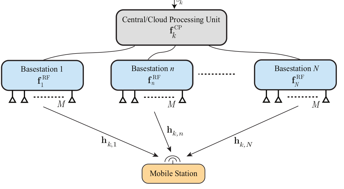
Figure 1. Coordinated Beamforming System Model
Here we assume that each user is served by several cooperating base stations (4 BSs is assumed in our work) where they collect both the directional and omnidirectional channel information to build the beamforming weights matrices. Each Base Station (BS) here is reporting its collected channel information to a central (or cloud) processing unit where all the calculations for the beamforming are done. For thesimulation purposes, the system is assumed to be deployed into a street environment as in the figure-2 with the base stations (BS1, BS2, BS3, BS4) serving a moving user (walking, running, biking, or riding a car user) in the street in between these base stations.
The system is assumed to be frequency-selective coordinated mmWave with the received signal at the subcarrier (k) after the precoding is expressed as:
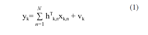
where: (xk,n) is the discrete time transmitted signal vector from the n-th BS at the k-th subcarrier, (hk,n) is the channel vector between the user and the n-th BS at the k-th subcarrier, and (vk) is the receive noise at subcarrier (k) defined as a normal distribution with a zero mean and (𝛔2) variance [3].
The assumed channel model is the same channel model assumed in [3] which can be expressed as in equation-2:
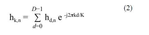
and

with the parameters defined as in [3].
DEEP MIMO DATASET AND SIMULATION PROCESS
The dataset used in this paper is collected using the DeepMIMO [6] tool available online with the features explained below. The number of base stations can be selected from a list of 18 base stations available in the original simulation environment [6]. In our experiments, we selected only (4) of these base stations named (BS1, BS2, BS3, and BS4) distributed as in fig 2 and fixed on lamp posts. The distance between BS1 and BS3 equals the distance between BS2 and BS4 and equals 100m. The distance between BS1 and BS2 (across the street) equals to the distance between BS3 and BS4 and equals to 40m. Each BS has a height of 6m from the ground level [6]. Each BS is assumed to have a uniform planar array (UPA) of antennas that are facing the street. The grid of expected user locations starts from row number R550 and ends with the row number R1100 with each row having 181 users. The total number of expected users’ locations in a uniform grid that is being collected for the full fingerprint is (99731) location. Each user location will be collected by 4 BSs with each having 16X4 MIMO antenna arrays. Also, for each user, 3 paths of the signal between the user and each BS is collected (LoS and the strongest 2 NLos or 3 NLoS if there is blockage of the LoS path). First, the dataset is collected using MATLAB according to the simulation parameters listed above and in table 1 and the steps in [3]. After generating the dataset that will represent the inputs and outputs of the deep learning model, we use python to build, train, and test the deep learning model with different settings as we will see in the next section. To achieve that, we need Python 3.6 or later with Keras and Tensorflow libraries support. Finally, we used MATLAB again to process the deep learning outputs and generate the performance results and figures listed in the next section. More details about the simulation process are listed in the DeepMIMO official website [18].
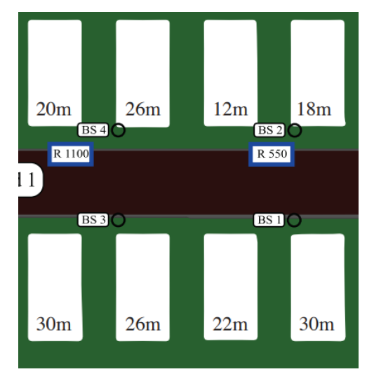
Figure 2. A top View of the street, buildings, and the Base stations distribution
5. NUMERICAL RESULTS
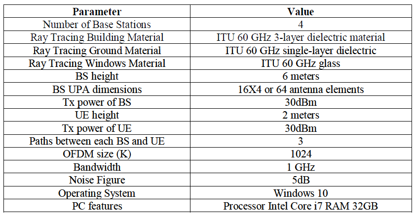
The system is assumed to serve a mobile user (walking in the street or driving a car among the serving Base stations) using the unlicensed mmWave band of 60GHz frequency and focuses on vehicular applications in a street environment. The table (1) is listing all the parameters used in the system simulation:
Table 1. Simulation Parameters
5.1. Mobility speed effect:
The first step in this work was to check the mobility speed effect on the performance of the system and we tried different speeds to check what would be the resulting spectral efficiency in (bits/sec/Hz). The figure (3) below shows that for different speeds (10, 50, and 100 mph), the deep learning network performance is almost the same and can still achieve a high system rate compared to the optimal genie-aided spectral efficiency. This means that the proposed network is stable for different mobility speeds and that it can be used for a wide range of mobile applications and scenarios.

Figure 3. UE Mobility Speed Effect on the Achievable Spectral Efficiency
5.2. Network Optimization:
To optimize the network performance (i.e. reduce the dataset required to achieve the best performance and the time required to train and use the model), we first changed some of the data collection assumptions where instead of collecting 5 or 8 rays (multipaths) for each transmission in the ray tracing software, we assumed that there are only 3 rays that are worth collecting taking in consideration the scarcity of the mmWave channel multipath and that only one Line of Sight (LoS) and the strongest 2 Non-Line of Sight (NLoS) multipaths are strong enough to express important information about the UE location and the rest will be too weak because of the reflections from trees, ground, and other environmental elements that degrades the mmWaves much faster than the lower frequencies (i.e sub-6GHz bands). Then we changed the neural network (used in the base stations to perform the beamforming) architecture to find the optimal structure for our goals. Several optimizers were tried first as follows:
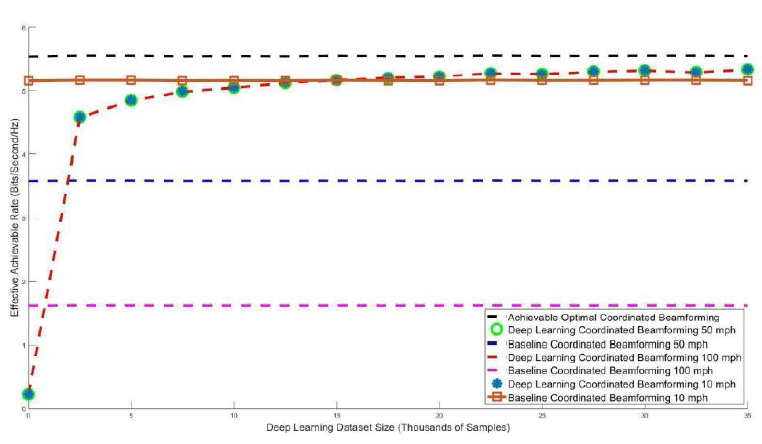
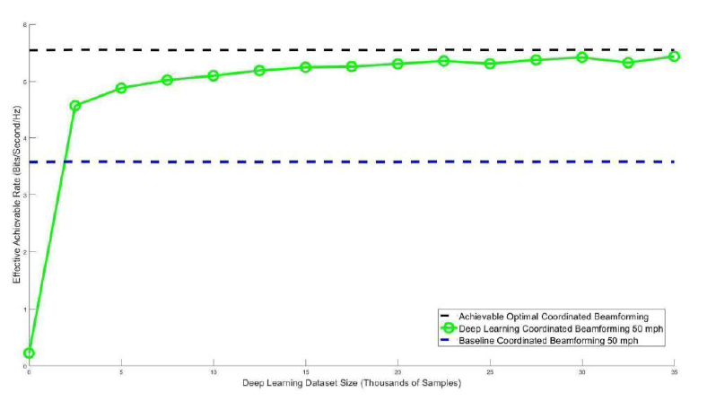
The originally selected optimizer by the paper [3] is Adam optimizer and it gives this result in figure 4:
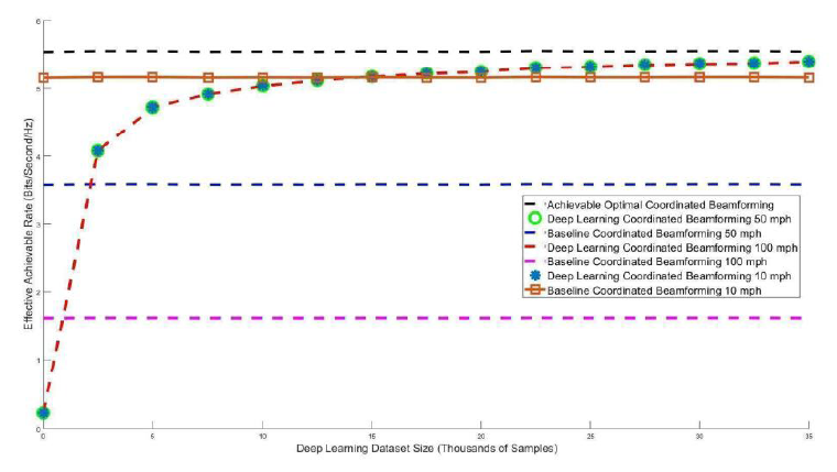
Figure 4. Achievable Spectral Efficiency with Adam optimizer
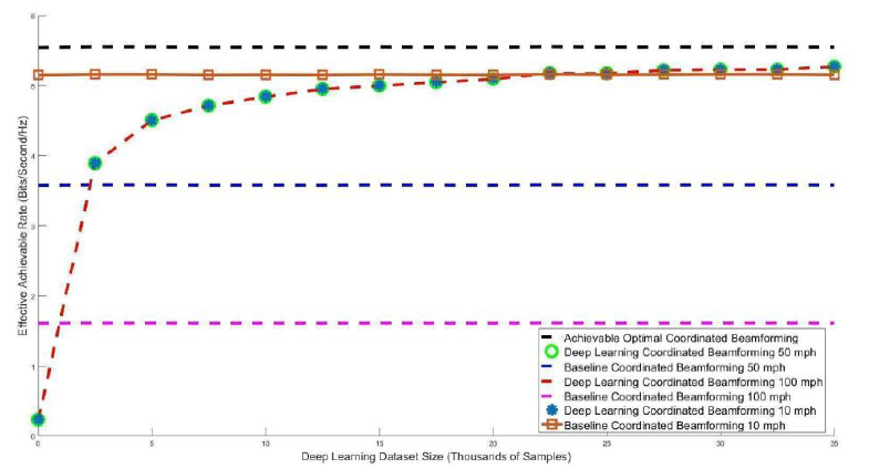
When we tried the optimizer (Ada Delta) instead of (Adam) optimizer, we got the results shown in figure 5 where we see that the neural network performed worse than that in the previous case:

The optimizer (Ada Grad) gave comparable performance to the (Adam) optimizer in terms of the spectral efficiency and the required dataset size to achieve the 90% threshold of the genie-aided beamforming performance in figure 6:
The optimizer (Ada Max) on the other hand gives worse performance compared to the (Adam) and (Ada Delta) optimizers as can be seen in figure 7 where it requires larger dataset to achieve close performance to the optimal upper bound (the genie-aided beamformer) :
The improved (Adam) optimizer or (Nadam) explained in details in [17] gives the best results among the tested optimizers both in case of spectral efficiency and the dataset size as we can see in figure 8 below:

Finally, the optimizer (RMS prop) is used and its results are listed in figure 9:

And we can see clearly that the optimizer (Nadam) achieves the threshold (90% of the genie aided spectral efficiency) faster than all the others. So, it is considered as the chosen optimizer and to further optimize the deep learning network, we tried several loss functions as follows:
Mean Squared Error (MSE) loss function was tried and it gave the same results as in figure 4. The Mean Squared Logarithmic Error (MSLE) was also tried with the results in figure 10:
Another loss function (Poisson loss function) was used in combination with the (Nadam) optimizer in the same neural network structure and the results of the achievable spectral efficiency of this NN structure compared with the all known (optimal) beamformer are shown in figure 11:

Whereas the results when using Mean Absolute Error (MAE) as the loss function with the (Nadam) optimizer are shown in figure 12 and they shown better performance than the previous NN structure (i.e Poisson loss function) but it is still not as good as the case when we used the (MSLE) loss function.
Mean Absolute Error loss function
Finally, the Mean absolute percentage error (MAPE) error function with (Nadam) optimizer performance compared with the genie-aided beamforming systems is shown in figure 13 where it shows the worst performance among all the NN structure we tried and that is why it is not recommended to build such applications.

It is clear that the (MSLE) achieves the best performance when combined with the (Nadam) optimizer, so they are selected to build the optimal deep neural network to produce the best model with the minimum dataset required and accelerate the training and operation of the collaborative beamforming system.
6. CONCLUSIONS AND FUTURE WORK
In this paper, deep learning coordinated beamforming that uses multiple collaborating base stations to perform the beamforming has been optimized and tested for different mobility scenarios. First the Neural Network structure and the data collection process was improved. Then, the best optimizer and loss function to give the best possible performance have been chosen for a broad range of mobility speeds and operation scenarios. The system has been proved to be resilient towards the mobility speed changing with time and that it can still be further improved. The reported results are also encouraging to go further and try to upgrade the system to work as a hybrid beamforming system. Some of the future work directions include: Generalizing the proposed beamforming architecture to multi users instead of serving only single users each time, improving the analog beamformer to a hybrid (analog phase shifter and digital base band) beamformer and for both single and multiple cooperative base stations, and test the adaptability of such systems in the connected cars/automated cars scenarios where there would be frequent handovers and huge amount of calculations in the backend of the system.
CONFLICTS OF INTEREST
The authors declare no conflict of interest.
REFERENCES
[1] Sakaguchi, K., Haustein, T., Barbarossa, S., Strinati, E. C., Clemente, A., Destino, G., … & Keusgen, W. (2017). Where, when, and how mmWave is used in 5G and beyond. IEICE Transactions on Electronics, 100(10), 790-808.
[2] Kutty, S., & Sen, D. (2015). Beamforming for millimeter wave communications: An inclusive survey. IEEE Communications Surveys & Tutorials, 18(2), 949-973.
[3] Alkhateeb, A., Alex, S., Varkey, P., Li, Y., Qu, Q., & Tujkovic, D. (2018). Deep learning coordinated beamforming for highly-mobile millimeter wave systems. IEEE Access, 6, 37328-37348.
[4] Lin, T., & Zhu, Y. (2019). Beamforming design for large-scale antenna arrays using deep learning. IEEE Wireless Communications Letters.
[5] Zhou, P., Fang, X., Wang, X., Long, Y., He, R., & Han, X. (2018). Deep learning-based beam management and interference coordination in dense mmWave networks. IEEE Transactions on Vehicular Technology, 68(1), 592-603.
[6] Alkhateeb, A. (2019). DeepMIMO: A generic deep learning dataset for millimeter wave and massive MIMO applications. arXiv preprint arXiv:1902.06435.
[7] Remcom, “Wireless insite,” http://www.remcom.com/wireless-insite
[8] Aljumaily, M. S., & Li, H. (2019, November). Machine Learning Aided Hybrid Beamforming in Massive-MIMO Millimeter Wave Systems. In 2019 IEEE International Symposium on Dynamic Spectrum Access Networks (DySPAN) (pp. 1-6). IEEE.
[9] Zhang, Menglei, et al. “Will TCP Work in mmWave 5G cellular networks?.” IEEE Communications Magazine 57.1 (2019): 65-71.
[10] Gatzianas, M., et al. “Downlink Coordinated Beamforming Policies for 5G Millimeter Wave Dense Networks.” 2019 European Conference on Networks and Communications (EuCNC). IEEE, 2019.
[11] Ahmed, Irfan, et al. “A survey on hybrid beamforming techniques in 5G: Architecture and system model perspectives.” IEEE Communications Surveys & Tutorials 20.4 (2018): 3060-3097.
[12] Gao, Zhen, et al. “MmWave massive-MIMO-based wireless backhaul for the 5G ultra-dense network.” IEEE Wireless Communications 22.5 (2015): 13-21.
[13] Bogale, Tadilo Endeshaw, and Long Bao Le. “Beamforming for multiuser massive MIMO systems: Digital versus hybrid analog-digital.” 2014 IEEE Global Communications Conference. IEEE, 2014.
[14] Yu, Xianghao, et al. “Alternating minimization algorithms for hybrid precoding in millimeter wave MIMO systems.” IEEE Journal of Selected Topics in Signal Processing 10.3 (2016): 485-500.
[15] Chen, Jung-Chieh. “Hybrid beamforming with discrete phase shifters for millimeter-wave massive MIMO systems.” IEEE Transactions on Vehicular Technology 66.8 (2017): 7604-7608.
[16] Aljumaily, Mustafa S. “Hybrid Beamforming in Massive-MIMO mmWave Systems Using LU Decomposition.” 2019 IEEE 90th Vehicular Technology Conference (VTC2019-Fall). IEEE, 2019.
[17] Tato, Ange, and Roger Nkambou. “Improving adam optimizer.” (2018).
[18] DeepMIMO: A Generic Deep Learning Dataset for Millimeter Wave and Massive MIMO Applications (http://www.deepmimo.net/?i=1).
AUTHORS

