
A Hybrid Modulation Method For Dimming In Visible Light Communication
Wataru Uemura and Takahiro Kitazawa
Department of Electronics and Informatics, Ryukoku University, Shiga, Japan
Abstract
In visible light communication in which information is superimposed on light, its communication range is visible. On the other hand, when the modulation that brightness is changed according to information is used, it is not good for the human eye because human feels flicker for the changed brightness. Therefore, the pulse width modulation which is used in the infrared remote controller, is not suitable for the visible light communication. And the pulse position modulation that sends information at the position of a pulse is often used. In pulse position modulation, for example, when one symbol uses four slots, quad information can be sent by turning on only one slot among the four slots and turning off the other three slots. In this method, the brightness becomes ¼ and feels not flicker but darker than when it is always on. On the other hand, when inverted pulse position modulation in which these slots of ON and OFF are reversed is used, since one slot is OFF, and three slots are ON, the brightness becomes 3/4, which does not become too dark. In this paper, we propose a hybrid modulation that can vary the brightness other than 1/4(25%) or 3/4(75%) by combining these pulse position modulation and inverted pulse position modulation. We have two experiments; one is measuring its communication performance and the other is the evaluation for visual flicker by the human eye and. From the view of the communication performance, each brightness is the same performance. So, the changing brightness does not affect to the performance. For the dimming, we interviewed 10 people how to feel the flicker in visible light communication. As the result, they do not feel the flickers. So, our proposed hybrid modulation method can be adapted for the dimming lighting equipment.
Keywords
Visible Light Communication, lighting control, dimming, wireless communication
1.Introduction
Visible light communication is one of the wireless communications in which carrier is the visible light band in the electromagnetic wave and information is encoded according to the changing pattern of blinking visible light [1-3]. The illuminations elements at home area and public area are changed to light emitting diodes (LEDs). Because the response speed of LEDs is very fast, so this lighting equipment can be used as transmitters for visible light communication [4-6]. While the communication range has a visible, flickering occurs due to a slow change in brightness, so a modulation that does not change the brightness depending on the information is required. Brightness perceived by human eyes has relationships of not only strength but also emission time. For example, a fluorescent lamp flashes with an alternating current like as 50Hz or 60Hz, but its blinking cannot be seen by the human eyes, and it seems that it is always turned on. On the other hand, in a broken fluorescent lamp, the accumulated luminescence intensity changes in unit time, so it feels flicker. Therefore, a pulse position modulation (PPM) method and an inverted pulse position modulation (i-PPM: i-PPM) method are generally used as a modulation method in which the cumulative emission intensity per unit time is constant.
For lighting equipment, it is necessary to freely change the brightness. This is called dimming. Although the brightness of the LED has depended on the magnitude of the flowing current, it is generally difficult to adjust the brightness because it is controlled by the voltage. Therefore, dimming for LED is performed by adjusting the pulse width as a pseudo-analog output. Generally, as a dimming control method for LED, a pulse width modulation (PWM) method is used in which changes the time ratio between ON and OFF [7]. The PWM method is an analog modulation method which is also used for controlling the servo motor angle but in VLC, analog information is not used and the brightness corresponds to the analog value. When visible light communication is applied to lighting equipment and PWM is selected for the modulation method, brightness changes according to information, and flickering occurs. On the other hand, when the PPM method or i-PPM method is selected for the modulation, flickering does not occur, but brightness cannot be changed.
In this paper, we propose the hybrid modulation method which can control the dimming light for visible light communication. In Section 2, we introduce the modulation method of visible light communication without flickering using pulse and propose a hybrid modulation method that can change the brightness of VLC in Section 3. The performance of the proposed modulation method is shown in Section 4 and we conclude this paper in Section 5.
2.Pulse Modulation Methods
In this section, we introduce the modulation method using pulses, for example, pulse width modulation (PWM), pulse position modulation (PPM), and inversed pulse position modulation (i-PPM).
2.1. Pulse Width Modulation (PWM)
The PWM method is a modulation method in which the time of HIGH that means the length of the carrier pulse is changed by the input signal (shown in Fig. 1). In one cycle, the duty ratio between HIGH and LOW changes according to the input signal. For example, when it is used as binary digital communication, we send information of “1” when the HIGH is long and information of “0 when the LOW is long


Figure 1. Information allocation by PWM method


Figure 2. Information allocation by 2-PPM method

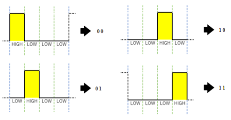
Figure 3. Information allocation by 4-PPM method
ce information can be decided if only HIGH time or LOW time can be detected in one cycle, the receiver circuit and program are very simple. However, since the light emission time of the LED is depended on the information, the power consumption is not stabilized, and in the case of visible light communication, flickering occurs.
2.2. Pulse Position Modulation (PPM)
The PPM method is a modulation method in which the position of the carrier pulse depends on the input signal. We can change the number of bits to send at the same time, when we change the number of slots and assign information according to the number of slots in the slot that means whether the slot is ON. For example, if we select to communicate as a binary digit, two slots are prepared, and information of “0” is assigned when the first slot is HIGH, and information of “1” when the second slot is HIGH (shown in Fig. 2).
When four slots are prepared, it becomes 4-PPM, and four kinds of information can be sent with one symbol (shown in Fig. 3). Therefore, 2 bits of information can be transmitted at the same time. In this case, depending on the combination of symbols, there may be unbalanced in the number of HIGH and LOW. However, from the viewpoint of the human eye, they do not feel flicker because the ratio of HIGH and LOW is constant. Therefore, it is highly good matching with lighting

Figure 4. Information allocation by inversed 4-PPM method
2.3. Inversed Pulse Position Modulation (i-PPM)
The i-PPM method is a modulation method in which HIGH and LOW of the PPM method are inverted. However, in the case of the binary PPM method, since the ratio of HIGH and LOW is 1:1, even if it is reversed, essentially it does not change. Brightness changes when the number of slots is four or more (shown in Fig. 4)
We do not feel flicker because the ratio of HIGH and LOW in one symbol is constant like as PPM. In addition, the brightness becomes higher since the time of HIGH becomes longer as using multiple slots. In the case where the time of one slot cannot be shorter due to the response speed of the LED elements or the light receiving elements, the communication speed is the same as the previous case. However, since the ratio of HIGH and LOW changes, the brightness changes.
2.3. Brightness
In general, “brightness” may have different meanings such as illuminance, luminance, luminous intensity, luminous flux and the like [8-9]. For example, the brightness indicates how lighter it looks when looking at the light source. In the case of luminous intensity, it indicates the amount of luminous flux per unit solid angle in a certain direction. The former is the brightness for the person seeing the light (receiver) and the latter is the brightness emitted by the light emitter (transmitter). Here, the difference between the brightness from the viewpoint of dimming and from the viewpoint of visible light communication is described.
2.3.1. Luminous Flux
The luminous flux represents the amount of energy that is perceived as light when entering the human eye, among the energy radiated from the light source. The unit is lm (lumens). In the LED data sheet and so on, lm / w is often used as a unit of luminous efficiency. If the value of the light flux becomes large, the light reaches far, and conversely, if it becomes small, the reaching distance becomes short. In visible light communication, the value of the light flux is proportional to the communication distance, and if it is the same distance, the greater the value of the light flux, the stronger the received light intensity, so the influence of noise becomes smaller. Therefore, the value of the light flux is greatly related to the performance of the communication.

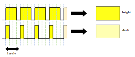
Figure 5. PWM dimming method
2.3.2. Illuminance
Illuminance indicates the amount of light flux irradiated per unit area. The unit is lx = lm / m2 [lux]. In the specifications of the lighting equipment, the value of the luminous flux is often listed since it is the performance of the luminous elements. However, since the brightness that human beings feel is the receiving sensitivity, it is the illuminance. Therefore, when actually using it as a lighting device, the value of the illuminance becomes important.
2.4. Dimming System
The dimming system is generally used such as stand type lighting equipment. Now we summarize these dimming control methods.
2.4.1. Dimming Control Using PWM
At first, we explain the dimming control method using the PWM method (shown in Fig. 5). In this method, dimming is performed by controlling the duty ratio within one period. It becomes bright when the ratio of HIGH is large and becomes dark when the ratio of LOW is large. Then, we can change dimming from 0% to 100%.

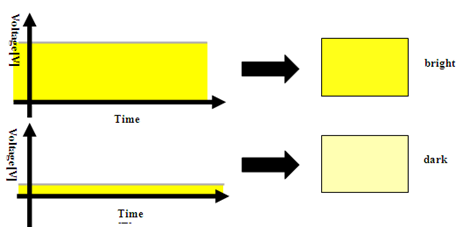
Figure 6. Analog dimming method


Figure 7. Phase control method
2.4.2. Dimming Control by the Supply Current of LED
Next, we explain the dimming control method that controls the supply current of LED by using a variable resistor (shown in Fig. 6). The current value flowing is controlled by the change in the resistance value. Since the brightness of the LED varies according to the current value, dimming is possible. If the voltage is constant, it is difficult to adjust the brightness since the resistance value and the current value is in inverse proportion.
2.4.3. Dimming Control by Cutting Out the Current Waveform Flowing
It is a dimming control method that cuts out the current waveform flowing to the light emitting element in one period of the AC waveform (shown in Fig. 7). The more the lamp current, or the shorter the waveform cutting time is, the brighter it is. The less the lamp current, or the longer the waveform cutting time is, the darker it is. The brightness is highly consistent with the incandescent lamp which is determined by the current value.
3.Proposed Mixed Pulse Position Modulation (M-PPM)
In this section, we focus on the 4 PPM method and the i-4 PPM method for dimming which make little flickers because the duty ratio is constant.
We propose a method to change the dimming of LED by making the combination of 4PPM and i-4PPM in some symbols. For example, we use four 4-PPM formats for the first 4 symbols and four i-4PPM formats for the second 4 symbols in order to send 8 symbols.
On the receiver side, input signals with mixed modulation are received; it is possible to determine which method is used by counting the number of HIGH and LOW for each symbol. This hybrid modulation enables visible light communication in which flicker does not occur and dimming can be performed. We call this modulation to mixed pulse position modulation (Mixed PPM)

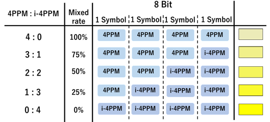
Figure 8. Mixed-PPM for 4 symbols can make the brightness
from 25% (same as 4-PPM) to 75% (same as i-4PPM).
4.Experiment and Results
In this section, we evaluate the proposed Mixed PPM method from the viewpoint of 1) communication and 2) dimming. In order to evaluate them, we have the experiment to measure the communicable distance and BER and we have the questionnaire about flicker at each dimming light. For this time, we assumed the transmission of 8-bit information and applied Mixed PPM method (Shown in Fig. 8).
For measuring the communication performance, we send 25,000 times 272-bit information for each dimming ratio. The transmitter element is the 10W power LED, which is X-Lamp XM-L made by Cree. The maximum illumination of it is 1040 [Lm] [10]. Figure 9 shows its circuit. The result is shown in Fig. 10.

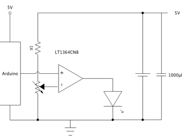
Figure 9. The transmitter circuit for visible light communication.


Figure 10. Error rate for distance in dimming rate
For the dimming, we interviewed 10 people how to feel the flicker during communication in visible light communication. We investigated whether to feel flicker when Mixed PPM method is applied or whether to feel flicker in case of PWM method as a comparison target by questionnaire. The result is shown in Fig. 11. At the ratio with 0:4, some people feel the flicker. But that ratio is the same as the ratio of PPM. So, the feeling flicker is not affected by the proposed hybrid method but the conventional method because of the slow modulation speed. Then the people do not feel the flicker by our proposed method.
5.Conclusion
In this paper, we focused on the brightness by the visible light communication. For changing brightness on lighting elements, PWM is used. But it occurred the flicker for sending the information. For avoiding flicker, PPM and i-PPM are used. But these modulation methods cannot change the brightness. We proposed a hybrid modulation method that enables dimming for visible light communication. Experiments on communication performance confirmed that the Mixed PPM method shows almost the same BER as compared with the conventional PPM method and i-PPM method. In the evaluation questionnaire concerning flicker, there were no voices that the proposed method feels flicker with respect to the PWM method.

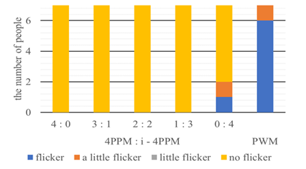
Figure 11. The interview result for 10 people feeling flicker for each dimming method.
References
[1] S. Haruyama,”Visible light communication”, Journal of IEICE (D), vol. 94, no. 12, pp. 1055 – 1059, 2011.
[2] Rajan Sagotra, “Visible Light Communication”, International Journal of Computer Trends and Technology (IJCTT) vol. 4, No. 4, pp. 906 – 910, 2013.
[3] Dominic C. O’Brien, “Visible Light Communications: challenges and possibilities”, PIMRC 2008. IEEE 19th International Symposium on Personal, Indoor and Mobile Radio Communications, pp.15 – 18, 2008.
[4] K. Okuda, T. Yamamoto, T. Nakamura, and W. Uemura, “The Key Providing System for Wireless Lan Using Visible Light Communication”, International Journal of Ad hoc, Sensor & Ubiquitous Computing (IJASUC), vol. 5, pp. 13 – 20, 2014.
[5] K. Okuda, H. Shirai, T. Nakamura, and W. Uemura, “A Novel Keyless Entry System Using Visible Light Communication”, International Journal of Ad hoc, Sensor & Ubiquitous Computing (IJASUC), vol. 5, pp. 1 – 8, 2014.
[6] K. Okuda, R. Yoneda, T. Nakamura, and W. Uemura, “A Warning System for Overspeed at the Corner Using Visible Light Based Road-To-Vehicle Communication”, International Journal of Ad hoc, Sensor & Ubiquitous Computing (IJASUC), vol. 6, pp. 1 – 9, 2015.
[7] I. Galkin, L. Bisenieks and A. Suzdalenko, “Impact of pulse modulation method of LED dimmer for street lighting on its efficiency”, 4th European Education and Research Conference (EDERC 2010), Nice, pp. 160 – 164, 2010.
[8] T. Saito, “A Study for flicker on Visible Light Communication”, Technical Report of IEICE CS, vol. 106, No. 450, pp. 31 – 35, 2007.
[9] I. Shouichi, “Reduction of Flicker by Coding and Modulation for Visible-Light Communication” Technical Report of IEICE OCS, vol. 108, No. 39, pp. 1 – 4, 2008.
[10] http://www.cree.com/led-components/products/xlamp-leds-discrete/xlamp-xm-l,2018-06-24 accessed
Authors

Wataru Uemura was born in 1977, and received B.E, M.E. and D.E. degrees from Osaka City University, in 2000, 2002, and 2005. He is an associate professor of the Department of Electronics and Informatics, Faculty of Engineering Science, Ryukoku University in Shiga, Japan. He is a member of IEEE, RoboCup and others.

Takahiro Kitazawa was born in 1996 and received Bachelor of Engineering degrees in 2018 from Ryukoku University in Shiga, Japan. He is a master course student in JAIST. He is interested in the security of Internet.

