
IJCNC 08
Modeling Low-Cost Inertial Navigation Systems and Their Errors
Mohammed AFTATAH, Khalid ZEBBARA and Soufiane EL ASRI
Laboratory of Research in Innovation in Mathematics and Intelligent Systems (IMIS), Faculty of Applied Sciences, Ibn Zohr University, BP: 523 Agadir, Morocco
Abstract
Inertial Navigation Systems (INS) are critical for a wide range of applications due to their ability to provide reliable navigation information, even without external references. This paper presents a comprehensive study of the modeling of low-cost INS sensors and their inherent errors, focusing on how these errors impact the accuracy of the system’s localization outputs. A MATLAB-based simulation platform was developed to analyze the effects of common sensor errors on position, velocity, and attitude over time. The experimental results show that these errors accumulate, leading to significant deviations from the true trajectory. Notably, the maximum positional error in the upward direction reached 65 meters by the end of the simulated trajectory, while the velocity error in the same direction deviated by 0.8 m/s. Initially, the estimated trajectory closely followed the reference path, but as the simulation progressed, a substantial divergence occurred, highlighting the cumulative impact of sensor errors. These findings underscore the necessity of advanced error mitigation techniques to enhance the long-term accuracy and reliability of INS in practical applications.
Keywords
Low-Cost Inertial Navigation System, Sensor errors, Navigation, Modeling, Mechanization
1. Introduction
During the last two decades, the utilization of navigation sensors has observed a significant demand in many areas especially in land vehicle applications [1]. These sensors can be used separately or in combination to improve navigation. They include LiDAR (Light Detection and Ranging) sensors [2] [3], GPS (Global Positioning System) [4], and Inertial Measurement Units (IMUs) [5] [6]. Historically, The GPS is recognized as the most accurate navigation system, making it a crucial component for several navigation systems used in intelligent technologies such as drones and land vehicles. However, GPS can provide location information only when the receiver has a connection to four or more satellites [7]. To put it more simply, the system’s performance is compromised in an urban environment due to signal blockage or attenuation, which can significantly degrade the accuracy of positioning [8].
Nowadays the majority of navigation systems combine two or more complementary positioning technologies to provide high precision for the smart system’s three-dimensional position and velocity [9]. One of the proposed solutions to overcome the issue of satellite signal degradation in urban environments is to fuse GPS data with inertial systems using various approaches, including Kalman filter GPS/INS integrated system [10][11][12], GPS/INS integration based on Extended Kalman filter [13][14][15] and Neural-Kalman GNSS/INS navigation [16]. most of these approaches, simulate navigation in urban environments where the blockage of GPS signals occurs [8]. Indeed, the inertial navigation unit is utilized to provide positioning information in the
absence of satellite systems. However, with inexpensive inertial sensors with elevated noisy outputs, the inertial navigation system will rapidly diverge during GPS outages, leading to a significant decrease in navigation precision
This paper will detail the common errors confronted in inertial navigation systems. These errors result from many factors, including drifts, bias, and scale factors. These errors tend to degrade the accuracy of the system’s navigation, especially during outages of external references such as GPS signals. A comprehensive and precise modeling of these errors is essential for effective correction, crucial to verifying inertial navigation across various applications. We present a novel approach by developing a comprehensive simulation platform for INS systems. Unlike traditional methods that require the purchase and integration of physical sensors for testing and validation, our platform allows for the complete simulation of INS behavior under various conditions. This approach offers several key advantages:
Cost Efficiency: By eliminating the need for expensive sensor hardware, our platform significantly reduces the costs associated with INS system development and testing;
Flexibility: The platform allows for easy modification and testing of different sensor models, error characteristics, and environmental conditions without the need for physical alterations or multiple hardware setups;
Rapid Prototyping and Testing: Developers can quickly iterate on different INS designs and error mitigation strategies, accelerating the development process and enabling more comprehensive testing across a wide range of scenarios;
Scalability: The platform can simulate large-scale scenarios involving multiple sensors and complex environments, which would be challenging and costly to replicate with physical systems;
Educational and Research Utility: The simulation platform serves as a valuable tool for educational purposes and for researchers who require a controlled environment to study INS behavior and develop new algorithms without the need for specialized equipment.
This paper is structured as follows: The first section is the introduction, which provides a brief description of the inertial navigation system (INS) and its various applications, highlighting the importance of such systems in modern technology. Section 2 offers a summary of existing works through a literature review, identifying research gaps and challenges that this work seeks to address. Section 3 discusses our proposed INS model, covering the modeling of the IMU, the modeling of INS errors, and the mechanization process for estimating navigation information. Section 4 presents our proposed approach. Section 5 describes the experimental setup realized in the Matlab environment. Section 6 presents the simulation results, applying our model to a reference trajectory and analyzing the outcomes. Section 7 concludes the paper by summarizing key findings. Finally, section 8 discusses future directions for expanding this research.
- Existing Works
2.1. Literature Review
In recent years, numerous studies have focused on mitigating errors in Inertial Navigation Systems (INS) by utilizing real INS units. Researchers have explored a variety of approaches, including the enhancement of sensor accuracy, the development of advanced filtering algorithms, and the integration of INS with other navigation systems like GPS. The authors of [17] analyzed the limitations of physical IMUs in dynamic environments, where motion-dependent errors accumulate, emphasizing the difficulty of maintaining accuracy without extensive corrections. Similarly, in [18] the authors highlighted the susceptibility of physical INS units to error
accumulation during GPS signal loss, demonstrating how neural networks can assist but still depend on the initial physical IMU accuracy. The researchers of [19] focused on sensor biases, revealing how physical IMUs’ inherent drift leads to significant long-term errors without external correction. In [20] the study underscores the challenges of relying on physical IMUs for sensor fusion, particularly in dynamic environments where errors from physical sensors can be difficult to mitigate. The work on [21] explores a gyro-free approach but notes that physical accelerometers still face noise and environmental sensitivity challenges. Meanwhile, [22] highlights the limitations of physical laser INS systems, particularly their susceptibility to environmental noise and drift, which improved filtering techniques aim to mitigate. In [23] the researchers examined the extreme conditions of aerobatic flight, showcasing the pronounced limitations of physical INS units during high-dynamic maneuvers where complex correction algorithms are necessary. In [24] the study addressed the variability in physical INS units’ performance, showing how multi-INS strategies can reduce but not fully eliminate inconsistencies without simulation tools. These traditional approaches to studying and mitigating these errors often involve using physical INS units, which can be costly, inflexible, and limited to the specific grade of the hardware available.
2.2. Research Gaps and Challenges
While inertial navigation systems offer promising solutions to mitigate several primary limitations of wireless-based navigation systems such as GPS and Galileo—especially in scenarios where satellite signals are intentionally or unintentionally blocked—there remain significant research gaps and challenges. Precise navigation estimation, relying on both signal-based systems and proprioceptive sensors, is crucial for effective integration. Various methodologies have emerged in recent years; however, they often suffer from limitations explained below.
- The primary challenge is the high cost of traditional INS systems, particularly high-grade INS, which can be prohibitively expensive for many research laboratories;
- The complexity and time required to install, configure, and re-deploy these systems across different vehicles hinder experimental flexibility;
- The bulk and size of physical INS units may also restrict their deployment in smaller or unconventional platforms;
- The wear and tear from repeated use of real INS units can degrade performance over time, increasing maintenance costs and introducing variability into experimental results.
Hence, the development of a platform combining both the modeling of INS and their inherent errors is presented in this work. This approach aims to address the cost and operational barriers by offering a more flexible and scalable solution that incorporates the accuracy of INS modeling while considering the typical errors.
2.3. Benefits of a Simulation Platform for INS Modeling
The reviewed literature highlights the challenges associated with using real INS for various applications, particularly in terms of cost, flexibility, and the ability to simulate different environments and sensor grades. By offering a simulation platform, our approach addresses these challenges, providing a cost-effective and flexible tool for researchers and engineers. The ability to adjust error parameters allows for the simulation of different grades of INS, enabling more comprehensive studies without the need for multiple physical systems. This flexibility makes simulation an attractive alternative to physical INS, especially for early-stage research and development.
This simulation technology offers a promising alternative by providing a platform where the inherent errors of INS can be modeled and manipulated virtually. This approach allows researchers and engineers to simulate different grades of INS by adjusting error parameters such as bias instability, scale factor errors, and noise characteristics without the need for multiple physical units. The flexibility of such a platform enables comprehensive analysis across a wide range of scenarios, making it an invaluable tool for both research and development.
3. INS Modeling
An inertial navigation system (INS) consists of two main parts: the inertial measurement unit (IMU) and the calculation unit. The IMU contains three gyroscopes and three accelerometers, covering the three dimensions, and providing raw sensor data. The calculation unit then uses these IMU measurements to estimate critical navigation information such as attitude, velocity, and position. This section details the development of our custom IMU model, including the accurate modeling of the gyroscopes and accelerometers. Additionally, it addresses the modeling of key errors that negatively impact the performance of these sensors, such as bias, noise, and scale factor errors. Finally, we describe the INS mechanization process, which is responsible for translating the IMU data into precise navigation estimates.
3.1. IMU Modeling
The chosen IMU to simulate is composed of three accelerometers and three gyroscopes. Thus, this simulation involves determining accelerations and angular velocities from 3D positions along the X, Y, and Z axes. The 3D positions are generated by a MATLAB code that simulates a vehicle’s trajectory. In this study, the ENU frame (East, North, Up) is used to express the IMU modeling equations. In the following, the ENU coordinate system will adopted as the navigation frame, also referred to as the n-frame. The body frame (b-frame) is situated at the center of the IMU. The IMU modeling equations in the n-frame are given by the following equations (1, 2, 3):

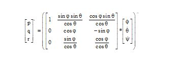

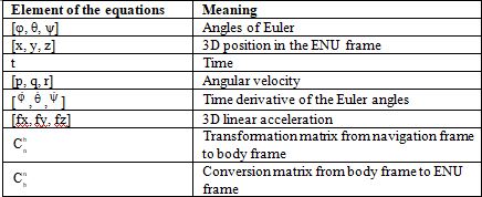
Table 1 summarizes the components of the equations above:
Table 1. The factors in the equations (1), (2), and (3).
3.2. IMU Errors Modeling
Certainly, the inertial navigation system provides a very high level of navigation availability compared to the GPS, given that it is embedded in the vehicle. However, several types of errors affect this system, namely: Bias, scale factor error, and noise. The following equations (4, 5) illustrate our modeling of the aforementioned errors:

Where
is measured by angular rate,
![]() is true angular rate,
is true angular rate,
is the gyroscope bias,
is the gyroscope noise,
is the gyroscope scale factor,
is measured by linear acceleration,
is true linear acceleration,
is the accelerometer bias,
is the accelerometer noise,
is the accelerometer scale factor.
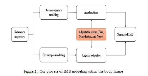
INS systems are utilized in several applications, so various grades of these systems are found on the market. These grades include consumer, industrial, tactical, and navigation. The table below shows the typical parameters for different grades of available inertial sensors. There exist other errors that influence the accuracy of dead-reckoning navigation using INS are not taken into consideration in this paper, including misalignments, temperature dependencies, and gyro g-sensitivity. The process of IMU modeling within the body frame is shown in Figure 1. This figure provides a visual summary of the IMU modeling process in our simulation. The developed platform allows us to adjust the values of the errors, either increasing or reducing them, to simulate different scenarios and assess their impact on system performance.
This paper focused primarily on the main INS errors, such as bias, noise, and scale factor, as these are the most significant contributors to overall system error. Temperature-induced drift, misalignment errors, and g-sensitivity were not included in the current model due to their relatively lower impact on the specific application scenarios we examined. However, future work will consider integrating these additional error sources to create a more comprehensive error model, particularly for environments where such factors are expected to influence INS performance more significantly.
3.3. INS Mechanization
The INS mechanization equations are utilized to derive navigation solutions—namely position, velocity, and attitude—from the measurements provided by inertial sensors, which include specific acceleration and angular rate. In this study, these mechanization equations are formulated within the ENU (East-North-Up) coordinate system, where the x-axis points East, the y-axis points North, and the z-axis points Up. Here, the ENU coordinate system serves as the navigation frame (n-frame). The body frame (b-frame), on the other hand, is centered at the INS. The dynamic equations governing the n-frame are expressed as shown in equation (6) [17, 25].

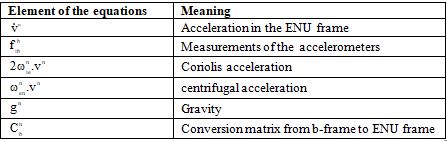
Table 2 summarizes the components of the equations (6):
Table 2. Equation (6) components.
The INS mechanization in the navigation frame is shown in Figure 2, adopted from [18, 26]:
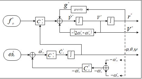
Figure 2. Mechanization of INS in the ENU frame
4. Proposed Approach
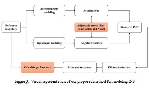
Our novel approach to modeling inertial navigation systems (INS) and their inherent errors is based on two fundamental components: accurate modeling of accelerometers and gyroscopes, and the exploitation of mechanization equations. The modeling process is carried out in a series of well-defined steps to ensure precision and adaptability. The first step involves generating the reference trajectory of a vehicle using MATLAB code. This trajectory is comprised of 3000 data points with coordinates X, Y, and Z in the ENU (East-North-Up) frame. The vehicle’s movement along this trajectory is not uniform; instead, its velocity varies as a result of acceleration and deceleration, allowing the model to simulate realistic dynamic behavior. This variability introduces a level of complexity that mimics real-world conditions, enhancing the robustness of the INS model by ensuring that it can handle changes in motion effectively.
The second step is dedicated to the detailed modeling of the six sensors that constitute the inertial system—three accelerometers and three gyroscopes. This sensor modeling captures the essential outputs of the system, namely accelerations in the body frame and angular rotations, which are critical for navigation computations. Once the sensor data is obtained, INS errors are intentionally added to the system outputs in the third step. The flexibility of our platform allows these errors to be varied dynamically without requiring any physical alterations to the system itself. This capability represents a significant advantage, as it facilitates a wide range of simulation scenarios by enabling the modification of error values to represent different operating conditions. Finally,
the mechanization equations of the INS are employed in the last step to process the sensor data and generate the 3D navigation data. This output provides comprehensive information about the vehicle’s position and orientation over time, making our platform a powerful tool for studying and simulating the behavior of INS in a variety of environments.
Figure 3 provides a comprehensive visual representation and detailed explanation of our proposed method for modeling inertial navigation systems (INS) and their inherent errors. It illustrates each stage of the process, beginning with the generation of a reference trajectory, followed by the modeling of the accelerometers and gyroscopes, the addition of varying INS errors, and culminating in the application of mechanization equations to produce 3D navigation data. The figure serves as a step-by-step guide that outlines the flow of data and the interaction between the different components of the system, highlighting the flexibility and adaptability of our platform in handling various error conditions without the need for physical modifications to the hardware.
5. Experimental Setup
The simulation scenario focuses on modeling the behavior of an inertial navigation system (INS) within an urban transport setting. The trajectory used for this simulation was carefully designed to replicate the complex motion of a vehicle navigating through an urban environment. It consists of a path that incorporates both straight segments and curved turns, reflecting the typical layout of urban streets, intersections, and roundabouts. The trajectory is composed of 3000 data points, defined by X, Y, and Z coordinates in the ENU (East-North-Up) frame, allowing for accurate representation of 3D movement.
The vehicle’s motion along this trajectory is not constant; instead, its velocity varies as the vehicle accelerates and decelerates at different points, simulating the real-world conditions of urban traffic, such as stops at traffic lights, turns at intersections, and variations in speed. These velocity changes introduce complexity in the dynamic behavior of the system, providing a realistic challenge for the INS. Additionally, the trajectory accounts for elevation changes, which are often present in urban environments due to bridges, tunnels, or uneven terrain.
This trajectory serves as the foundation for evaluating the performance of the INS, allowing us to observe how well the system can navigate through a diverse range of urban transport conditions, where signal degradation or loss (due to buildings or tunnels) may occur. The variability in the
path, coupled with the ability to dynamically adjust sensor errors, enables a thorough simulation of urban navigation challenges.
Figure 4 provides a detailed visual illustration of the reference trajectory used in the simulation, presented in both 2D and 3D perspectives. The 2D view offers a clear representation of the vehicle’s movement along the X and Y axes. In contrast, the 3D view adds depth to the trajectory by incorporating the Z axis, which represents the elevation changes that occur throughout the vehicle’s journey. This perspective allows for a more comprehensive visualization of the vehicle’s motion in all three dimensions—highlighting variations in altitude, such as uphill and downhill segments, bridges, and underpasses that are common in urban settings.
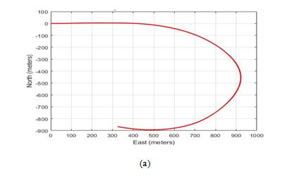
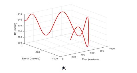
Figure 4. Overview of the ground truth involving both straight and curved paths in 2D (a) and 3D (b)
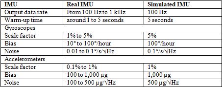
The performance characteristics of the simulated IMU adopted in this paper are presented in Table 3 below.
Table 3. Performance characteristics of the simulated IMU compared to real IMU
6. Simulation Results & Validation
During the experiment setup, the values of errors impacting the INS are adjusted according to the values shown in Table 3.
6.1. Errors in Positioning
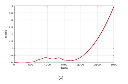
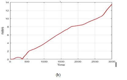
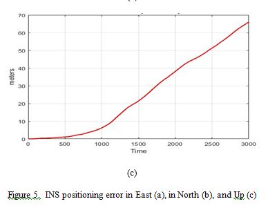
As shown in Figure 5, the errors in position estimated by the INS grow exponentially over time, particularly in the east, north, and up directions. These errors are proportional to the duration of the trajectory, with specific deviations calculated at the end of ground truth. For example, the errors reach 4 meters in the east direction, about 14 meters in the north direction, and as much as 65 meters in the up direction. The up direction experiences the largest error due to fluctuations in the gravity field, which significantly affect altitude estimation, leading to higher deviations compared to the horizontal directions.
6.2. Errors in Velocity
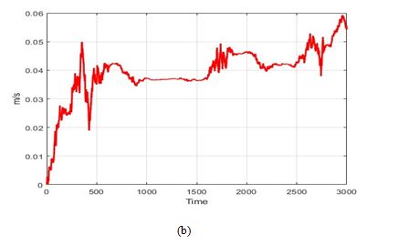
Figure 6 illustrates the calculated velocity errors by comparing the estimated values with the reference values obtained from the reference trajectory. It is evident that these errors not only affect position but also velocity, leading to the accumulation of deviations over time, similar to what is observed in position errors. The velocity errors follow a pattern where the east direction exhibits the smallest errors, followed by the north direction, while the largest errors are recorded in the up direction. The magnitude of errors in the up direction reaches 0.12 m/s at its maximum during the trajectory. However, the magnitude of velocity errors is not as pronounced as in the position errors, because velocity is derived by differentiating position concerning time, which smooths the impact of positional deviations.


6.3. Errors in Attitude
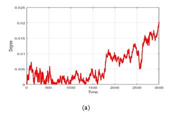
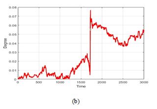
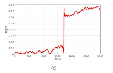
Figure 7 illustrates the errors in attitude estimation for roll, pitch, and yaw angles, which are essential for the overall accuracy of the inertial navigation system. These errors accumulate over time due to inherent sensor inaccuracies and misalignments. As depicted, roll and pitch errors are relatively modest, with maximum deviations at the end of the trajectory of 0.02 degrees and 0.05 degrees, respectively. In contrast, yaw angle errors are more pronounced, particularly over this extended trajectory, with a maximum deviation of 0.08 degrees at the end of the estimated trajectory. This larger yaw error is attributed to increased susceptibility to gyroscope drift.
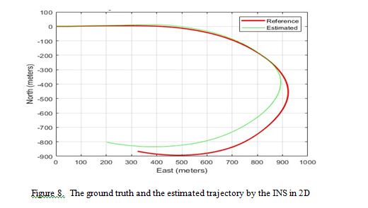
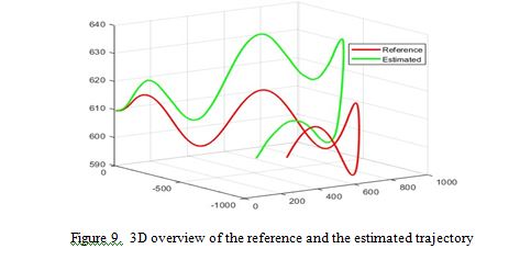
As shown in Figures 8 and 9, the estimated trajectory closely followed the reference path for a short time at the beginning. However, as time progressed, the trajectory began to deviate significantly from the reference, ultimately leading to a substantial discrepancy between the two paths by the end of the simulation. This divergence illustrates the cumulative impact of sensor errors on the accuracy of the INS over time, emphasizing the need for effective error mitigation strategies to ensure reliable navigation performance over extended periods.
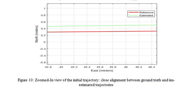
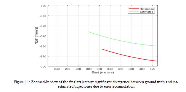
The results depicted in Figure 10, which shows a zoomed-in view of the beginning of the trajectory, reveal that the reference trajectory and the one estimated by the INS are almost indistinguishable, indicating that the errors at this stage are negligible and do not exceed 0.5 meters in the north direction. However, Figure 11, also a zoomed-in view, focuses on the endpoint of the trajectory, where a significant divergence between the reference and the INS-estimated trajectory is evident. The errors in the east and north directions reach 22 and 35 meters, respectively. This divergence is primarily due to the accumulation of errors in the INS over time, a common issue with inertial navigation systems as small errors in velocity and orientation can compound, leading to substantial positional drift. The greater error in the north direction compared to the east is likely due to the specific alignment of the INS sensors or the movement dynamics, which can cause more significant drift along one axis depending on the trajectory and external forces experienced during the navigation process.
The results demonstrate the impact of cumulative errors on the INS. In the initial phase of the trajectory, the close alignment between the reference and INS-estimated paths indicates minimal error. However, as the trajectory progresses, the divergence becomes significant, particularly in the north and east directions. This growing disparity highlights the inherent limitation of INS in long-duration operations, where small sensor errors accumulate over time, leading to substantial positional drift. These findings underscore the need for robust error correction mechanisms, such as sensor fusion with external data sources or the integration of machine learning models, to enhance INS accuracy and reliability in real-world applications.
6.4. Validation
To validate the accuracy of our simulation platform, we compared the simulated INS trajectory with real-world INS data obtained from a similar setup documented in previous work. Figure 12 illustrates a divergence between the reference trajectory and the trajectory estimated by the INS in the real world, which closely mirrors the behavior observed in our simulation results. This comparison demonstrates that our simulation platform effectively replicates the error patterns
seen in real-world INS systems, providing confidence in the platform’s ability to accurately model the behavior of actual inertial sensors under various conditions.

7. Conclusion
In this paper, we introduced the Inertial Navigation System as a pivotal system in various applications due to its high availability and reliability, even in environments where other navigation systems may fail. The modeling of INS sensors, along with their inherent errors, was thoroughly discussed to provide a comprehensive understanding of the factors that influence system accuracy. We developed a MATLAB-based simulation platform to quantify the impact of the most common errors encountered in inertial sensors on the localization information provided by such a system. Our experiments demonstrate that these errors increase and accumulate over time, significantly affecting navigation information, including position, velocity, and attitude. Specifically, the maximum error in the upward position direction reached 65 meters by the end of the estimated trajectory, indicating a substantial impact on position accuracy. Additionally, the velocity exhibited a slight deviation, reaching 0.8 m/s in the upward direction. These findings underscore the critical need for error modeling and mitigation in INS to maintain accuracy, especially over extended periods of operation.
8. Future Work
In future work, we plan to mitigate these errors by employing artificial intelligence approaches to develop a predictive model capable of accurately identifying and quantifying various sources of error in the inertial sensor information. This model will implement correction algorithms designed to minimize these errors in real-time at the output of such systems. A brief review of potential error mitigation techniques highlights several methods currently available in the literature. These include integrating inertial navigation systems (INS) with satellite-based systems like GPS or GNSS using Kalman filters, which help both to correct INS errors and to overcome GPS outages. The use of different types of Kalman filters, from standard KF to more advanced variants like the Unscented Kalman Filter (UKF), is well documented. Additionally, integrating INS with odometry or LiDAR systems provides further error correction capabilities. Another promising avenue involves AI-based techniques, where models such as Convolutional Neural Networks (ConvNet) and Gated Recurrent Units (GRU) are trained using labeled data from a trusted system, such as reference trajectories from high-grade INS or GPS. These models are then
employed to correct INS errors, offering a powerful tool for enhancing the accuracy and reliability of navigation systems in complex environments.
Conflicts of Interest
The authors declare no conflict of interest.
Acknowledgements
The authors would like to thank everyone, just everyone!
References
[1] Hecker, P., Angermann, M., Bestmann, U. et al, (2019) “Optical Aircraft Positioning for Monitoring of the Integrated Navigation System during Landing Approach”, Gyroscopy Navig. 10, 216–230.
[2] Li N, Guan L, Gao Y, Du S, Wu M, Guang X, Cong X, (2020), “Indoor and Outdoor Low-Cost Seamless Integrated Navigation System Based on the Integration of INS/GNSS/LIDAR System”, Remote Sensing. 12(19):3271.
[3] Abdelaziz N, El-Rabbany A, (2022) “An Integrated INS/LiDAR SLAM Navigation System for GNSS-Challenging Environments”, Sensors. 22(12):4327.
[4] Zhanke He, Erhu Wei, Qiyuan Zhang, Lingxuan Wang, Yanlin Li, Jingnan Liu, (2023) “Earth rotation parameters from BDS, GPS, and Galileo data: An accuracy analysis”, Advances in Space Research, Volume 71, Issue 10, Pages 3968-3980.
[5] Boguspayev N, Akhmedov D, Raskaliyev A, Kim A, Sukhenko A, (2023) “A Comprehensive Review of GNSS/INS Integration Techniques for Land and Air Vehicle Applications”, Applied Sciences. 13(8):4819.
[6] K. Zhu, C. Deng, F. Zhang, H. Kang, Z. Wen and G. Guo, (2023) “A Multi-Source Fusion Navigation System to Overcome GPS Interruption of Unmanned Ground Vehicles”, IEEE Access, vol. 11, pp. 61070-61081.
[7] Mohamad Hashim IS, Al-Hourani A, (2023) “Satellite-Based Localization of IoT Devices Using Joint Doppler and Angle-of-Arrival Estimation”, Remote Sensing. 15(23):5603.
[8] Shengyu Li, Xingxing Li, Huidan Wang, Yuxuan Zhou, Zhiheng Shen, (2023) “Multi-GNSS PPP/INS/Vision/LiDAR tightly integrated system for precise navigation in urban environments”, Information Fusion, Volume 90, Pages 218-232.
[9] Zhang Y, Sun H, Zhang F, Zhang B, Tao S, Li H, Qi K, Zhang S, Ninomiya S, Mu Y, (2023) “Real-Time Localization and Colorful Three-Dimensional Mapping of Orchards Based on Multi-Sensor Fusion Using Extended Kalman Filter”, Agronomy. 13(8):2158.
[10] Yuelin Yuan, Fei Li, Jialiang Chen, Yu Wang, and Kai Liu, (2023) “An improved Kalman filter algorithm for tightly GNSS/INS integrated navigation system”, MBE, 21 (1): 963–983.
[11] K. Si, P. Li, Z. -P. Yuan, K. Qiao, B. Wang and X. He, (2023) “Distributionally Robust Kalman Filtering for INS/GPS Tightly Coupled Integration With Model Uncertainty and Measurement Outlier”, IEEE Transactions on Instrumentation and Measurement, vol. 72, pp. 1-13.
[12] H. Zhang, H. Xiong, S. Hao, G. Yang, M. Wang and Q. Chen, (2024) “A Novel Multidimensional Hybrid Position Compensation Method for INS/GPS Integrated Navigation Systems During GPS Outages”, IEEE Sensors Journal, vol. 24, no. 1, pp. 962-974, 1 Jan.1.
[13] Yin Z, Yang J, Ma Y, Wang S, Chai D, Cui H, (2023) “A Robust Adaptive Extended Kalman Filter Based on an Improved Measurement Noise Covariance Matrix for the Monitoring and Isolation of Abnormal Disturbances in GNSS/INS Vehicle Navigation”, Remote Sensing. 15(17).
[14] Qingdong Wu; Chenxi Li; Tao Shen; Yuan Xu, (2023) “Improved Adaptive Iterated Extended Kalman Filter for GNSS/INS/UWB-Integrated Fixed-Point Positioning”, CMES-Computer Modeling in Engineering & Sciences, Vol 134, Issue 3, p1761.
[15] Ibrahim A, Abosekeen A, Azouz A, Noureldin A, (2023) “Enhanced Autonomous Vehicle Positioning Using a Loosely Coupled INS/GNSS-Based Invariant-EKF Integration”, Sensors; 23(13).
[16] Yayun Du, Swapnil Sayan Saha, Sandeep Singh Sandha, Arthur Lovekin, Jason Wu, S. Siddharth, Mahesh Chowdhary, Mohammad Khalid Jawed, Mani Srivastava, (2023) “Neural-Kalman GNSS/INS Navigation for Precision Agriculture”, IEEE International Conference on Robotics and Automation (ICRA 2023) May 29 – June 2.
[17] Krystian Borodacz, Cezary Szczepański, (2023) “Impact of Motion-Dependent Errors on the Accuracy of an Unaided Strapdown Inertial Navigation System,” Sensors, Volume 23, Issue 7, Article 3528.
[18] Yabo Wang, Ruihan Jiao, Tingxiao Wei, Zhaoxing Guo, Yueyang Ben, (2024) “A Method for Predicting Inertial Navigation System Positioning Errors Using a Back Propagation Neural Network Based on a Particle Swarm Optimization Algorithm,” Sensors, Volume 24, Issue 12, Article 3722.
[19] Weixing Qian, Jiaqi Zhao, Jiayi Dong, Tianxiao Shen, (2023) “Visual–Inertial Navigation System Based on Virtual Inertial Sensors,” Applied Sciences, Volume 13, Issue 12, Article 7248.
[20] Shiquan Guo, Haibo Yu, Zhaoyuan Zhang, (2020) “Gyro-Free Inertial Navigation Systems Based on Linear Opto-Mechanical Accelerometers,” Sensors, Volume 20, Issue 12, Article 3357.
[21] Min Wang, Yulin Zhang, Wei Li, (2023) “Filter Design for Laser Inertial Navigation System Based on Improved Particle Filters,” Applied Sciences, Volume 13, Issue 5, Article 1236.
[22] Christian Reimer, Tim Schneider, Michael Stock, (2017) “INS/GNSS Integration for Aerobatic Flight Applications and Aircraft Motion Surveying,” Sensors, Volume 17, Issue 5, Article 941.
[23] Le Bao, Wenqi Li, Kyoosik Shin, Changsoo Han, (2024) “A Planar Multi-Inertial Navigation Strategy for Autonomous Systems for Signal-Variable Environments,” Sensors, Volume 24, Issue 4, Article 1064.
[24] Zhe Tian, Qian Zhang, Rui Wang, (2021) “Navigation Error Analysis in Strapdown Inertial Navigation Systems,” Sensors, Volume 21, Issue 15, Article 5142.
[25] Jiang W, Wang L, Niu X, Zhang Q, Zhang H, Tang M, Hu X, (2014) “High-Precision Image Aided Inertial Navigation with Known Features: Observability Analysis and Performance Evaluation”, Sensors; 14(10).
[26] Wu, Fan & Luo, Haiyong & Jia, Hongwei & Zhao, Fang & Xiao, Yimin & Gao, Xile, (2020) “Predicting the Noise Covariance With a Multitask Learning Model for Kalman Filter-Based GNSS/INS Integrated Navigation”, IEEE Transactions on Instrumentation and Measurement. PP. 1-1. 10.1109/TIM.2020.3024357.
[27] Duan, Yabo, Huaizhan Li, Suqin Wu, and Kefei Zhang, (2021) “INS Error Estimation Based on an ANFIS and Its Application in Complex and Covert Surroundings”, ISPRS International Journal of Geo-Information 10, no. 6: 388.
Authors
Mohammed AFTATAH obtained a diploma of engineering in Network and Telecommunications from ENSA Marrakech, Cadi Ayyad University, Marrakech, Morocco. Presently, he is a trainer at OFPPT in Network, Systems, and Cybersecurity and is actively pursuing his Ph.D. in Artificial Intelligence and its application to secure navigation for intelligent systems.
Dr. Khalid ZEBBARA earned his Ph.D. in Computer Systems from Ibn Zohr University, Agadir, Morocco. He is currently a Professor at the Faculty of Applied Sciences, Ibn Zohr University, Agadir. In addition, he heads the Imaging, Embedded Systems, and Telecommunications (IMIS) research team at the Faculty of Applied Sciences, Ibn Zohr University, Agadir.
Soufiane EL ASRI obtained a diploma in Software Engineering and Systems Integration from the Faculty of Science and Technology of Mohammedia, Hassan II University, Casablanca, Morocco. He is currently a senior software engineer at the National Road Safety Agency (NARSA) and is actively pursuing a Ph.D. in Artificial Intelligence with a focus on applications to enhance road safety systems.

